Gas Fired Lead Pot Canopy Hood
Text Version
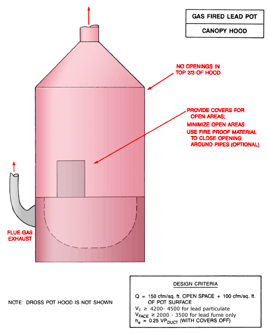
Gas Fired Lead Pot Canopy Hood
Gas fired lead pot canopy hood with flue gas exhaust and no openings in the top 2/3 of hood. Provide covers for open areas. Minimize open areas. Use fireproof material to close opening around pipes (optional).
Note: Dross pot hood is not shown.
Design Criteria:
Q = 150 cfm/ft2 open space + 100 cfm/ft2 of pot surface
Vt ³ 4,200 - 4,500 for lead particulate
Vface ³ 2,000 - 3,500 for lead fume only
he = 0.25 VPduct (with covers off)
Oxide Drum Filling Local Exhaust Ventilation
Text Version
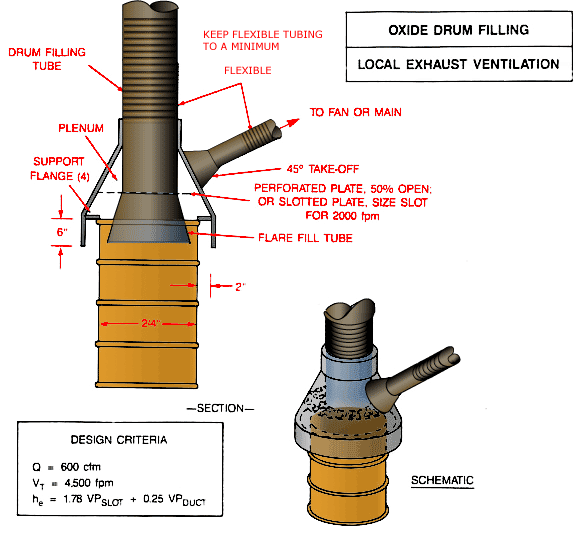
Oxide Drum Filling Local Exhaust Ventilation
Oxide drum with drum filling tube, plenum, perforated plate (50% open) or slotted plate (size slot for 2000 fpm), flare fill tube, and flexible tubing to fan or main with 45% take-off. A schematic view is also included.
Design Criteria:
Q = 600 cfm
Vt = 4,500 fpm
he = 1.78 VPslot + 0.25 VPduct
Oxide Barrel Filling Local Exhaust Ventilation
Text Version
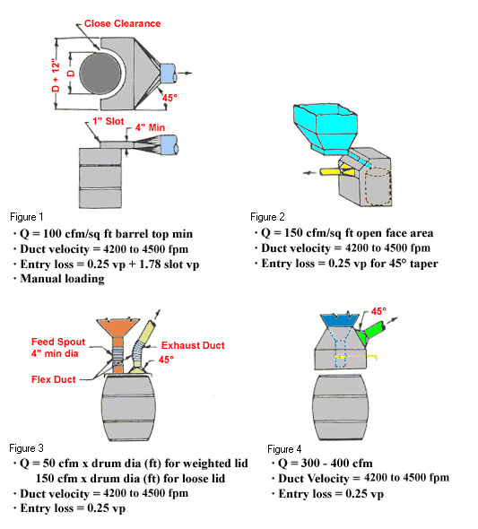
Oxide Barrel Filling Local Exhaust Ventilation
Side views of four barrel figures
Design Criteria:
- Figure 1 with 1" slot
- Q = 100 cfm/ft2 barrel top minimum
- Duct velocity = 4,200 to 4,500 fpm
- Entry loss = 0.25 vp + 1.78 slot vp
- Manual Loading - Figure 2
- Q = 150 cfm/ft2 open face area
- Duct velocity = 4,200 to 4,500 fpm
- Entry loss = 0.25 vp for 45° taper - Figure 3 with feed spout and exhaust duct
- Q = 50 cfm x drum dia (ft) for weighted lid
- Q = 150 cfm x drum dia (ft) for loose lid
- Duct velocity = 4,200 to 4,500 fpm
- Entry loss = 0.25 vp - Figure 4
- Q = 300 - 400 cfm
- Duct velocity = 4,200 to 4,500 fpm
- Entry loss = 0.25 vp
Toxic Material Belt Conveying Head Pulley
Text Version
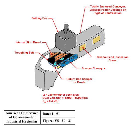
Toxic Material Belt Conveying Head Pulley
Totally enclosed conveyor with settling box, internal skirt board, troughing belt, return belt scraper or brush, scraper conveyor and cleanout and inspection doors. Leakage factor depends on type of construction.
Design Criteria:
Q = 250 cfm/ft2 of open area
Duct velocity = 4,200 - 4,500 fpm
he = 0.4 VPd
From American Conference of Governmental Industrial Hygienists (ACGIH®), Figure VS-50-21, Industrial Ventilation : A Manual of Recommended Practice, 23rd Edition. Copyright 1998. Reprinted with permission.
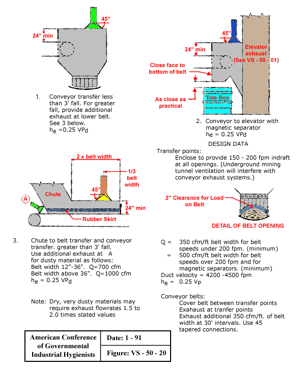
Conveyor Belt Ventilation
Text Version
Conveyor Belt Ventilation
Conveyor Types:
- Conveyor transfer less than 3' fall. For greater fall, provide additional exhaust at lower belt (see #3).
he = 0.25 VPd - Conveyor to elevator with magnetic separator.
he = 0.25 VPd - Chute to belt transfer and conveyor transfer, greater than 3' fall. Use additional exhaust for dusty material as follows:
Belt width 12"-36", Q = 700 cfm
Belt width above 36", Q = 1,000 cfm
he = 0.25 VPd
Note: Dry, very dusty materials may require exhaust flowrates 1.5 to 2.0 times stated values.
Design Data:
- Transfer points:
Enclose to provide 150 - 200 fpm indraft at all openings. (underground mining tunnel ventilation will interfere with conveyor exhaust systems.) - Detail of Belt Opening. 2" Clearance for load on belt.
- Q = 350 cfm/ft belt width for belt speeds under 200 fpm. (minimum)
Q = 500 cfm/ft belt width for belt speeds over 200 fpm and for magnetic separators. (minimum)
Duct velocity = 4,200 - 4,500 fpm
he = 0.25 VPd - Conveyor Belts:
Cover belt between transfer points
Exhaust at transfer points
Exhaust additional 350 cfm/ft of belt width at 30' intervals. Use 45° tapered connections.
From American Conference of Governmental Industrial Hygienists (ACGIH®), Figure VS-50-20, Industrial Ventilation: A Manual of Recommended Practice, 23rd Edition. Copyright 1998. Reprinted with permission.
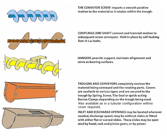
Screw Conveyor Components
Text Version
Screw Conveyor Components
The Conveyor Screw imparts a smooth positive motion to the material as it rotates within the trough.
Couplings and Shaftconnect and transmit motion to the subsequent screw conveyors. Held in place by self-locking Tem-U-Lac bolts.
Hangers provide support, maintain alignment and serve as bearing surfaces.
Troughs and Conveyors completely enclose the material being conveyed and the rotating parts. Covers are available in various types and are secured to the trough by spring, screw, tite-seal, or quick-acting barron clamps, depending on the trough being used. Also available as in a tubular configuration with no cover required.
Inlet and Discharge Openings may be located wherever needed, discharge spouts may be without slides or fitted with either flat or curved slides. These slides may be operated by hand, rack and pinion gears, or by power.
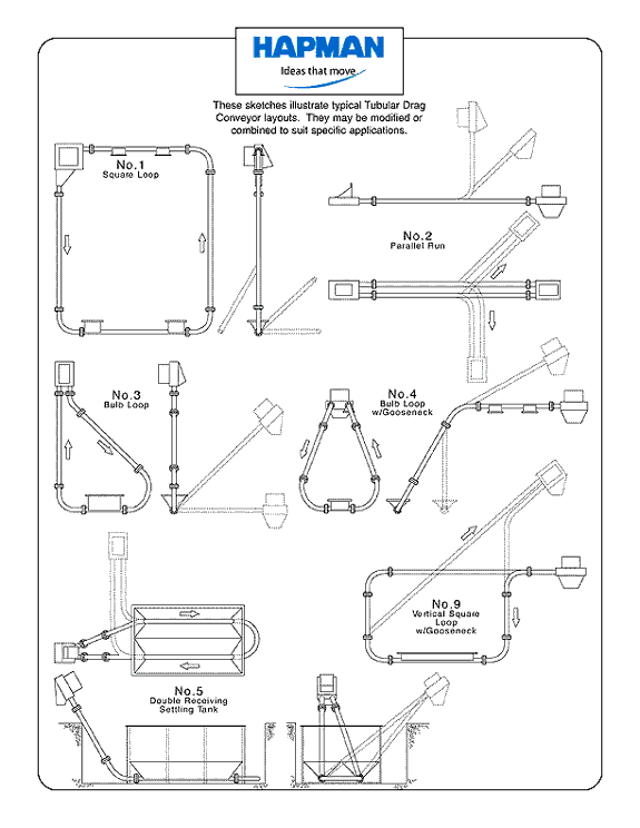
Drag Link Conveyor Configurations (Part 1)
Text Version
Drag Link Conveyor Configurations (Part 1):
- Square Loop
- Parallel Run
- Bulb Loop
- Bulb Loop w/ Gooseneck
- Double Receiving Settling Tank
- Vertical Square Loop w/ Gooseneck
These sketches illustrate typical tubular drag conveyor layouts. They may be modified or combined to suit specific applications
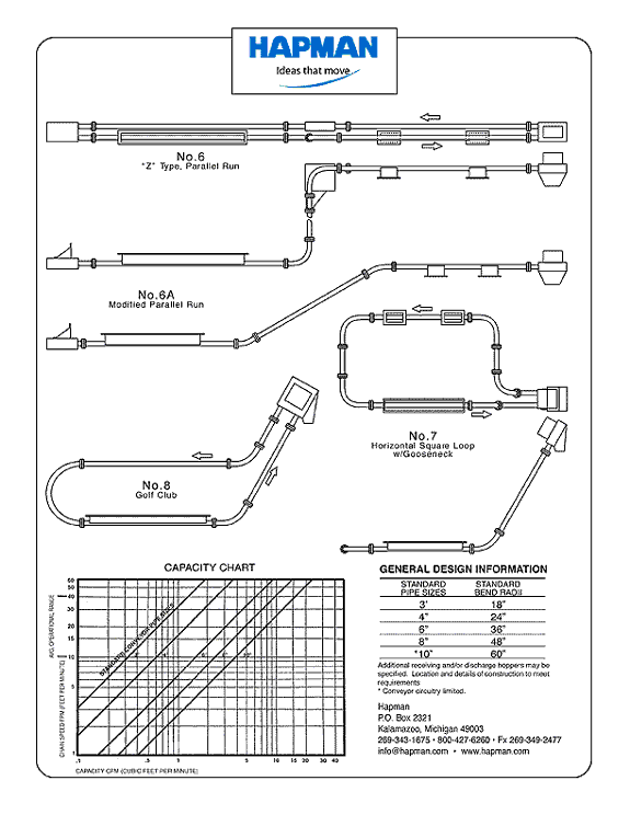
Drag Link Conveyor Configurations (Part 2)
Text Version
Drag link Conveyor Configurations (Part 2)
Drag Link Conveyor Configurations:
- "Z" type, Parallel Run
- A. Modified Parallel Run
- Horizontal Square Loop w/ Gooseneck
- Golf Club
- Capacity Chart
- General Design Information
These sketches illustrate typical tubular drag
conveyor layouts. They may be modified or combined to suit specific applications
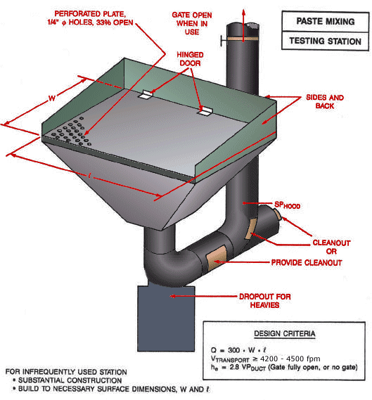
Paste Mixing Testing Station
Text Version
Paste Mixing Testing Station
Paste mixing test station with hinged door and perforated plate on hood and dropout for heavies. Gate open when in use.
Design Criteria:
Q = 300 x W x L
Vtransport ³ 4,200 - 4,500 fpm
he = 2.8 VPduct (Gate fully open, or no gate)
For infrequently used station:
- Substantial construction
- Build to necessary surface dimensions, W and L
Ventilated Tamping Stand
Text Version
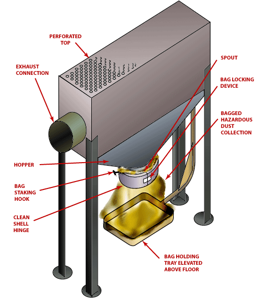
Ventilated Tamping Stand
Ventilated tamping stand with perforated top, exhaust connection, hopper, bag staking hook, clean shell hinge, spout, bag locking device, bagged hazardous dust collection, and bag holding tray elevated above floor.
Lead Pot and Dross Hood
Text Version
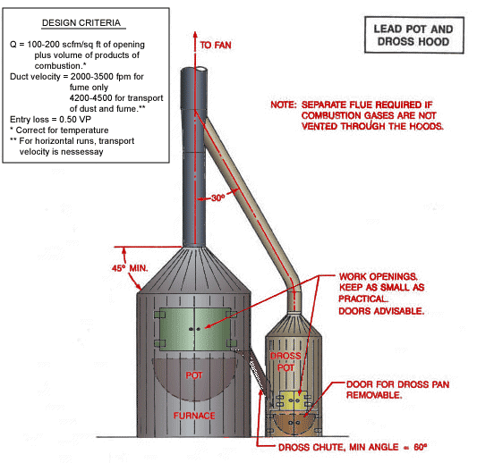
Lead Pot and Dross Hood
Lead pot with dross pot and hood. Keep work openings as small as practical. Doors advisable. Door for dross pan removable.
Design Criteria:
Q = 100 - 200 cfm/ft2 of opening plus volume of products of combustion.*
Duct velocity = 2,000 - 3,500 fpm for fume only.
Duct velocity = 4,200 - 4,500 fpm for transport of dust and fume.**
Entry loss = 0.50 VP
* Correct for temperature
** For horizontal runs, transport velocity is necessary.
Note: Separate flue required if combustion gases are not vented through the hoods.
Scrap Pot and Dross Hood
Text Version
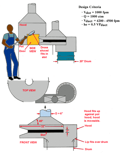
Scrap Pot and Dross Hood
Side view, top view and front view of scrap pot and dross hood. Dross shovel fits in slot. Side view shows pot door. Front view shows slot in hood with lip fitting over drum. Hood fits up against pot hood; hood is moveable.
Design Criteria:
Vslot = 1,000 fpm
Q = 1,000 cfm
Vduct = 4,200 - 4,500 fpm
he = 0.5 VPduct
Ventilated Torch
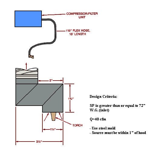
Text Version
Ventilated Torch
Compressor/filter unit with flex hose. Post burning portable tool exhaust.
Design Criteria:
SP is greater than or equal to 72"
W.G. (inlet)
Q = 40 cfm
- Use steel mold
- Source must be within 1" of hood
Scrap Handling Barrel/Drum Exhaust Hood
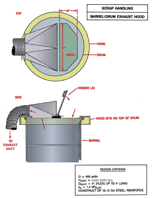
Text Version
Scrap Handling Barrel/Drum Exhaust Hood
Top view of hood and drum; Side view of barrel, with hood sitting on top of drum, with hinged lid open showing flow of air to exhaust duct.
Design Criteria:
Q @ 400 cfm
Vduct @ 4,200 - 4,500 fpm
Dduct = 4" (flex) up to 4' long
he = 1.4 VPduct
Construct of 10-12 gauge steel; reinforce
Pasting Station with Combined Supplied Air Island (SAI) and Exhaust
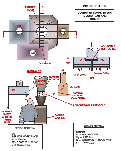
Text Version
Pasting Station with Combined Supplied Air Island(SAI)and Exhaust
Top view of combined supplied air island and exhaust. Side view with rotating hopper, plastic sheet around three sides of the supplied air island (SAI), with coarse screen and exhaust. Side curtains as feasible. A side view of the supplied air island (SAI) shows adjustable inlet baffle with 2-3 plates 30-50% open.
Design Criteria:
- Supplied Air Island
- Size for work place
- Vf = 150 fpm
- SP ³ 0.2 - 0.3" w.g at "A"
- Q ~ Qexhausted - Exhaust
- Size for process
- Vd = 4,500 fpm
- Q = 300 cfm/ft2 hood face
- he = 1.0 VPduct
Integrated Controls Plate Take-Off Operation
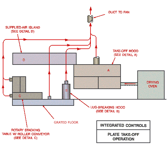
Text Version
Integrated Controls Plate Take-Off Operation
Plate take-off operation with drying oven, take-off hood, lug breaking hood and rotary stacking table with roller conveyor mounted on grated floor, with supplied air island mounted above.
Detail A - Take-off hood
Detail B - Lug-breaking hood
Detail C - Rotary stacking table w/ roller conveyor
Detail D - Supplied air island
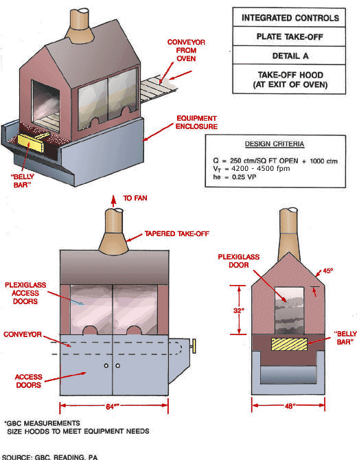
Detail A Integrated Controls Plate Take-Off Hood
Text Version
Detail A Integrated Controls Plate Take-Off Hood
Isometric view of detail A plate take-off hood with conveyor from oven, belly bar and equipment enclosure. Front view with access doors, conveyor, plexiglass access doors, tapered take-off hood to fan. Side view with belly bar and plexiglass door.
Design Criteria:
Size hoods to meet equipment needs
Q = 250 cfm/ft2 open + 1,000 cfm
Vt = 4,500 cfm
he = 0.25 VP
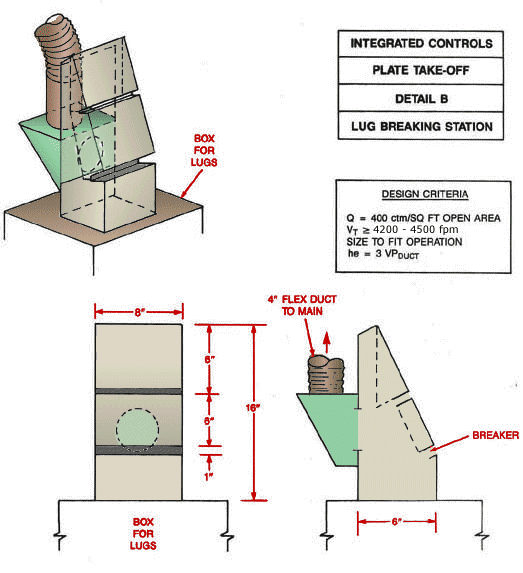
Detail B Integrated Controls Plate Take-Off Lug Breaking Hood
Text Version
Detail B Integrated Controls Plate Take-Off Lug Breaking Hood
Lug breaking hood showing box for lugs, 4" flex duct to main and breaker.
Design Criteria:
Q = 400 cfm/ft2 open area
Vt ³ 4,200 - 4,500 fpm
Size to fit operation
he = 3 VPduct
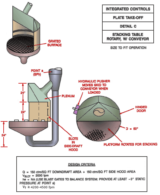
Detail C Integrated Controls Plate Take-Off Rotary Stacking Table with Conveyor
Text Version
Detail C Rotary Stacking Table with Conveyor
Isometric view of rotary stacking table showing grated surface. Side view showing plenum, slots in side-draft hood and point a. Top view showing hinged door, platform rotates for stacking and hydraulic pusher moves skid to conveyor when loaded.
Design Criteria:
Q = 150 cfm/ft2 downdraft area + 150 cfm/ft2 side hood area
Vslot = 2,000 fpm
he = NA (Use blast gates to balance system; provide at least -5" static pressure at point "a")
Vt ³ 4,500 fpm
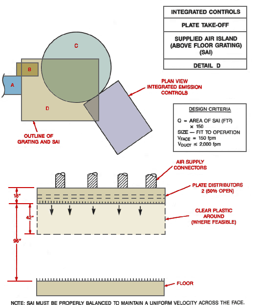
Detail D Integrated Controls Plate Take-Off Supplied Air Island
Text Version
Detail D Integrated Controls Plate Take-Off Supplied Air Island
Top view of supplied air island. Detail D is the outline of grating and supplied air island (SAI). The side view shows connectors, plate distributors 2 (50% Open) with clear plastic around where feasible. Supplied Air Island (above floor grating) (SAI)
Design Criteria:
Q = area of SAI (ft2) x 150
Size to fit operation
Vface = 150 fpm
Vduct £ 2,000 fpm
Note: SAI must be properly balanced to maintain a uniform velocity across the face.
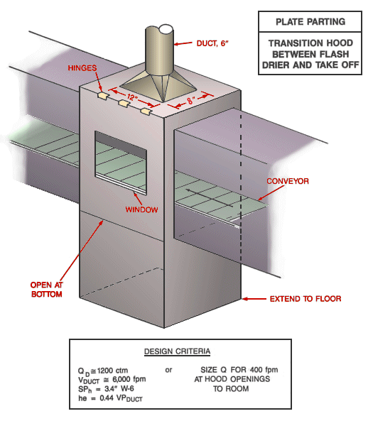
Plate Parting Transition Hood Between Flash Drier and Take Off
Text Version
Plate Parting Transition Hood Between Flash Drier and Take Off
Plate parting transition hood between flash drier and take-off shown with conveyor, window, duct and hinges. It is open at the bottom and extends to the floor. The top is hinged.
Design Criteria:
Qd @ 1,200 cfm
Vduct @ 6,000 fpm
SPh = 3.4" W-6
he = 0.44 VPduct
OR
Size Q for 400 fpm at hood openings to room
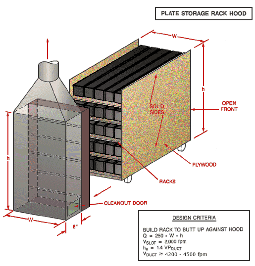
Plate Storage Rack Hood
Text Version
Plate Storage Rack Hood
Build rack with solid plywood sides, open front and internal racks butt up against hood with cleanout door.
Design Criteria:
Build rack to butt up against hood
Q = 250 x W x h
Vslot = 2,000 fpm
he = 1.4 VPduct
Vduct ³ 4,200 - 4,500 fpm
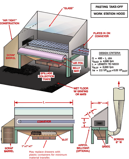
Pasting Take-Off Work Station Hood
Text Version
Pasting Take-Off Work Station Hood
Isometric view of pasting take-off work station hood showing spillage collection trays, air foil, belly bar, scrap barrel, plates in conveyor, "glass", "air tight" construction and wet floor with grating or mats. The front view shows the scrap barrel, the 1" X 1" X 1" slot, the conveyor and notes that the drawers may be replaced with plastic containers for minimum material transfer. The side view shows the airfoil belly bar (optional), the grate, and the 6" screen. The dimensions are given for the hood enclosure: 25" width, 14" height and 4" clearance of the glass.
Design Criteria:
Q = 400 x L cfm
Vduct ³ 4,500 fpm
L = Length to need
Vslot = 2,000 fpm
he = 2.3 VPslot + 0.25 VPduct
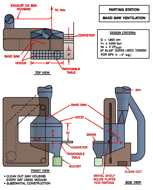
Parting Station Band Saw Ventilation
Text Version
Parting Station Band Saw Ventilation
Top view band saw, hoods, removable table, conveyor, exhaust on saw housing to fan. Front view of band saw, hood, removable table, conveyor, and bucket. Clean out saw housing every day using vacuum. Substantial construction. Side view with grate and swivel shelf holds plates for parting.
Design Criteria:
Q = 1,800 cfm
Vt ³ 5,000 fpm
he = 3 VPduct
(if blast gates used, design for SPh ³ -4" w.g.)
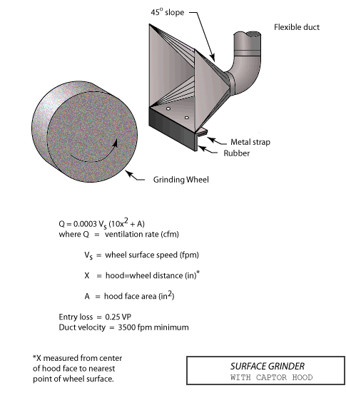
Surface Grinder with Captor Hood
Text Version
Surface Grinder with Captor Hood
Surface grinder with captor hood and flexible duct, 45 degree slope, metal strap and rubber shown.
Design Criteria:
Q = 0.0003 Vs (10X2 + A)
Where Q = Ventilation rate (cfm)
Vs = Wheel surface speed (fpm)
X = Hood/wheel distance (in)*
A = Hood face area (in2)
Entry loss = 0.25 VP
Duct Velocity = 3,500 fpm minimum
*X measured from center of hood face nearest point of wheel surface.
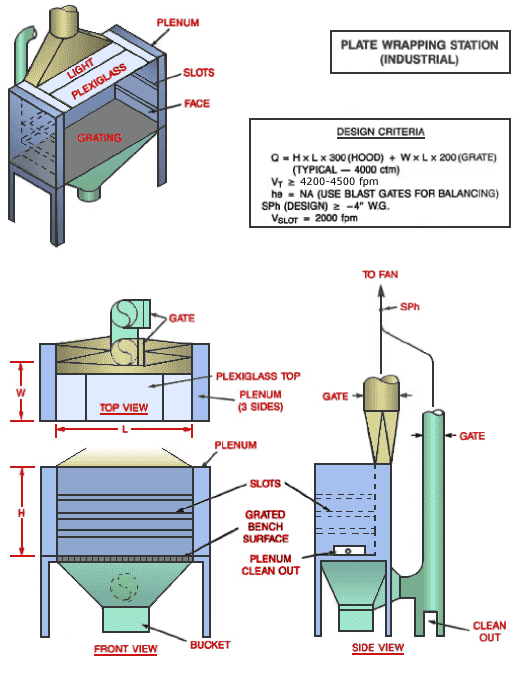
Plate Wrapping Station (Industrial)
Text Version
Plate Wrapping Station (Industrial)
Plate wrapping station with grating, plexiglass and light. Plenum, slots and face also shown. Top view, front view and side view with gate cleanout.
Design Criteria:
Q = H x L x 300 (Hood) + W x L x 200 (Grate)
(Typical - 4,000 cfm)
VT ³ 4,200 - 4,500 fpm
he = NA (Use blast gates for balancing)
SPh (Design) ³ -4" W.G
Vslot = 2,000 fpm
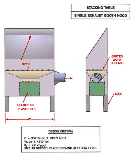
Stacking Table Single Exhaust Booth Hood
Text Version
Stacking Table Single Exhaust Booth Hood
Stacking table with single exhaust booth hood showing openings, bucket or plastic bag, legs and grated work surface.
Design Criteria:
Q = 3,000 cfm/ft2 open area
Vduct ³ 4,500 fpm
he = 2.0 VPduct
Size as needed; place opening at elbow level
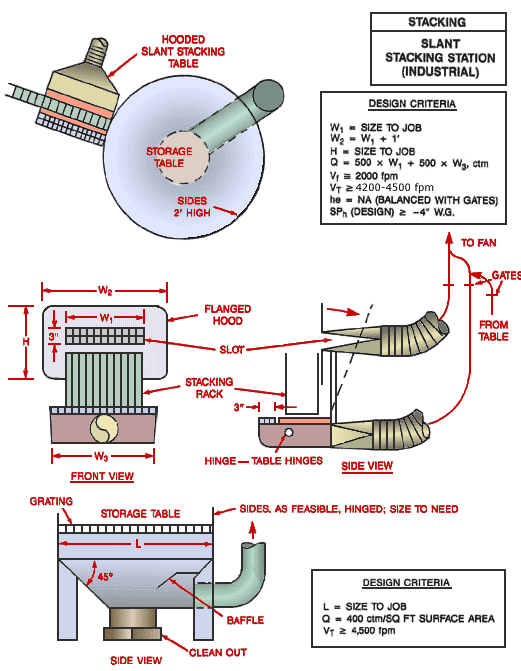
Slant Stacking Station (Industrial)
Text Version
Slant Stacking Station (Industrial)
Top view of hooded slant stacking station with storage table. Front view with flanged hood, slot, and stacking rack shown. Side view of storage table with grating, baffle and clean out. Sides as feasible, hinged. Size to need.
Design Criteria:
W1 = Size to job
W2 = W1 + 1'
H = Size to job
Q = 500 x W1 + 500 x W3 cfm
Vf @ 2,000 fpm
Vt ³ 4,500 fpm
he = NA (Balanced with gates)
SPh (Design) ³ -4" w.g.
L = Size to Job
Q = 400 cfm/ft2 surface area
Vt ³ 4,500 fpm
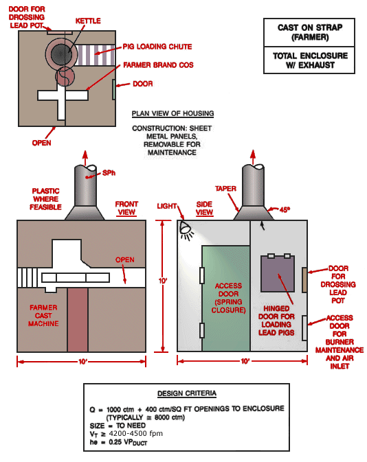
Cast on Strap Machine (Farmer) Total Enclosure with Exhaust
For problems with accessibility in using figures and illustrations, please contact the Directorate of Technical Support and Emergency Management at (202) 693-2300.
Text Version
Cast on Strap Machine (Farmer) Total Enclosure with Exhaust
Plan view of housing showing door for drossing lead pot, kettle, pig loading chute. Construction: sheet metal panels, removable for maintenance. Front view and side view showing access door with spring closure, hinged door for loading lead pigs, door for drossing lead pot and access door for burner maintenance and air inlet.
Design Criteria:
L = Size to Job
Q = 1,000 cfm + 400 cfm/ft2 opening to enclosure (Typically @ 8,000 cfm)
Size = To need
Vt ³ 4,000 fpm
he = 0.25 VPduct
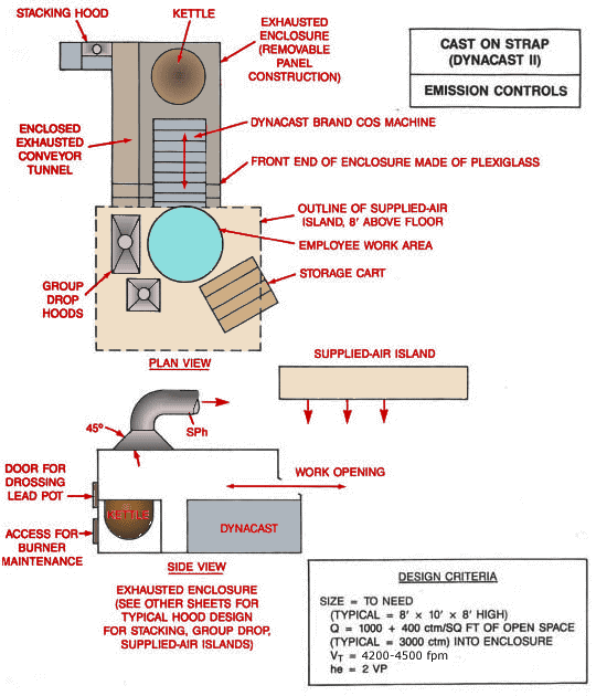
Cast on Strap Machine (Dynacast II) Emission Controls
Text Version
Cast on Strap Machine (Dynacast II) Emission Controls
Plan view with stacking hood, kettle, exhausted enclosure (removable panel construction), enclosed exhausted conveyor panel, front end of enclosure made of plexiglass, outline of supplied air island, employee work area, group drop hoods, and storage cart. Side view with supplied air island, door for drossing lead pot, access for burner maintenance, kettle, work opening and Dynacast.
Exhausted enclosure (See other sheets for typical hood design for stacking, group drop, supplied air islands.)
Design Criteria:
Size = To need
(Typical = 8' x 10' x 8' high)
Q = 1,000 + 400 cfm/ft2 of open space
(Typical = 3,000 cfm) into enclosure
Vt = 4,200 - 4,500 fpm
he = 2 VP
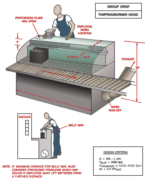
Group Drop Tamping/Burner Hood
Text Version
Group Drop Tamping/Burner Hood
Tamping burner hood showing employee work location, perforated plate 40%, screen and slot, and taper take-off. Side view of employee reaching over belly bar for battery at tamping burner hood location.
Note: 3" Maximum distance for belly bar. Must consider ergonomic problems which may occur if employee must lift batteries from a further distance.
Design Criteria:
Q = 650 x L cfm
Vslot = 2,000 fpm
Vtransport ³ 4,200 - 4,500 fpm
he = 2.2 VPduct
Note: 3" maximum distance for belly bar. Must consider ergonomic problems which may occur if employee must lift batteries from a further distance.
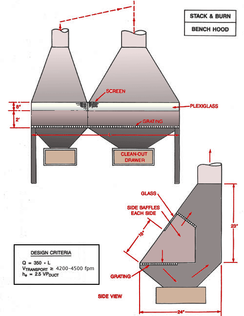
Stack and Burn Bench Hood
For problems with accessibility in using figures and illustrations, please contact the Directorate of Technical Support and Emergency Management at (202) 693-2300.
Text Version
Stack and Burn Bench Hood
Front view of stack and burn bench hood with screen, plexiglass, grating and clean-out drawer shown. Side view with side baffles, glass and grating shown.
Design Criteria:
Q = 350 x L
Vtransport ³ 4,500 fpm
he = 2.5 VPduct
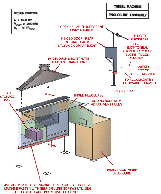
Tiegel Machine Enclosure Assembly
Text Version
Tiegel Machine Enclosure Assembly
Teigel Machine with 10" diameter duck and blast gate to 4" X 60" transition, plate storage box, hinged plexiglass and sliding bolt with adjustment holes. Reject container enclosure shown. Also Section AA detail showing side view of hinged plexiglass, slot to slot seal against 1 1/2" X 42" slot in tiegel machine.
Match 2 1/2 X 42" Slot against 1 1/3" X 40" slot in Tiegel Machine. Fasten with self-drilling screws utilizing felt gasket around perimeter of slot.
Design Criteria:
Q = 6,000 cfm
Vduct ³ 4,500 cfm
he ~ 1.5 VPduct
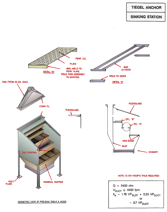
Tiegel Anchor Sinking Station
Text Version
Tiegel Anchor Sinking Station
Isometric view at pre-sink table and hood with bar grating, feet plate and nominal hopper. Ventilation hood pieces shown in Detail A: Perforated plate. Weld this assembly to grating and Detail B: Bar hood with weld to sides. Internal view with plexiglass and location of detail A and B.
Design Criteria:
Q = 2,400 cfm
Vduct ³ 4,500 fpm
he ~ 1.78 VPslot + 0.25 VPduct or
he ~ 0.7 VPduct
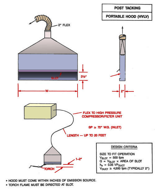
Post Tacking Portable Hood (HVLV)
Text Version
Post Tacking Portable Hood (HVLV)
Front and side view of post tacking portable hood with flex to high pressure compressor/filter unit. Length may be up to 20 feet.
Design Criteria:
Size to fit operation
Vslot @ 500 fpm
Q = Vslot x area of slot
he = 0.35 VPduct
Vduct ³ 4,500 fpm (typically 2")
- Hood must come within inches of emission source.
- Torch flame must be directed at slot.
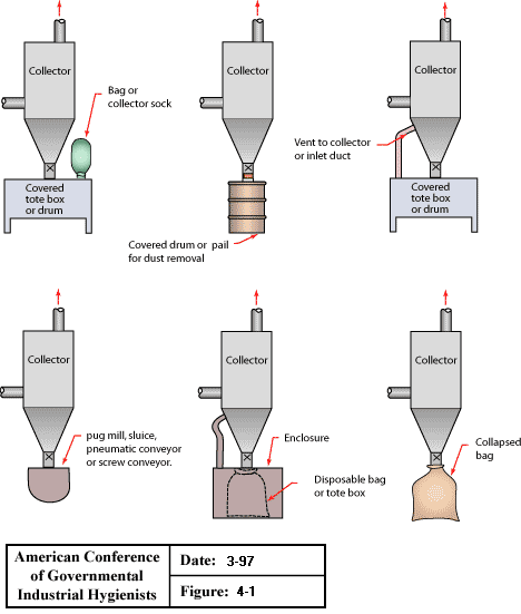
Dry Type Dust Collectors Dust Disposal
Text Version
Dry type dust collectors dust disposal:
- Covered tote box or drum with bag or collector sock
- Covered drum or pail for dust removal
- Covered tote box or drum with vent to collector or inlet duct
- Pug mill, sluice, pneumatic conveyor or screw conveyor to collector
- Disposable bag or tote box with enclosure to collector
- Collapsed bag to collector
From American Conference of Governmental Industrial Hygienists (ACGIH®), Figure 4-1, Industrial Ventilation : A Manual of Recommended Practice, 23rd Edition. Copyright 1998. Reprinted with permission.
Dry Type Dust Collectors Discharge Valves (Part 1)
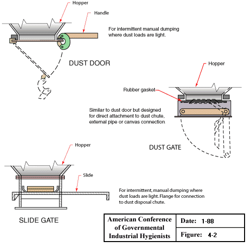
Text Version
Dry Type Dust Collector Discharge Valves (Part 1):
- Dust door with hopper and handle - For intermittent manual dumping where dust loads are light.
- Dust gate with hopper and rubber gasket - Similar to dust door but designed for direct attachment to dust chute, external pipe, or canvas connections.
- Slide gate with hopper and slide - For intermittent, manual dumping where dust loads are light. Flange for connection to dust disposal chute.
From American Conference of Governmental Industrial Hygienists (ACGIH®), Figure 4-2, Industrial Ventilation : A Manual of Recommended Practice, 23rd Edition. Copyright 1998. Reprinted with permission.
Dry Type Dust Collectors Discharge Valves (Part 2)
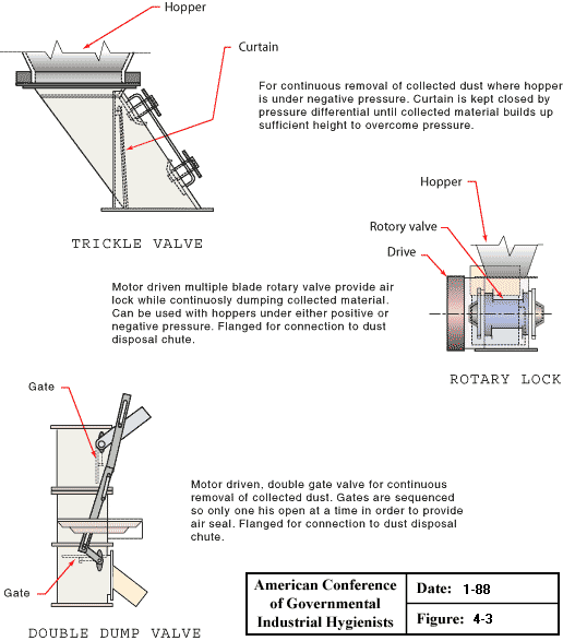
Text Version
Dry Type Dust Collector Discharge Valves (Part 2):
- Trickle valve with hopper and curtain- For continuous removal of collected dust where hopper is under negative pressure. Curtain is kept closed by pressure differential until collected material builds up to sufficient height to overcome pressure.
- Rotary lock with hopper, rotary valve and drive - Motor driven multiple blade rotary valve provide air lock while continuously dumping collected material. Can be used with hoppers under either positive or negative pressure. Flanged for connection to dust disposal chute.
- Double dump valve with gate - Motor driven, double gate valve for continuous removal of collected dust. Gates are sequenced so only on is open at a time in order to provide air seal. Flanged for connection to dust disposal chute.
From American Conference of Governmental Industrial Hygienists (ACGIH®), Figure 4-3, Industrial Ventilation : A Manual of Recommended Practice, 23rd Edition. Copyright 1998. Reprinted with permission.
Flexible Exhaust Connections
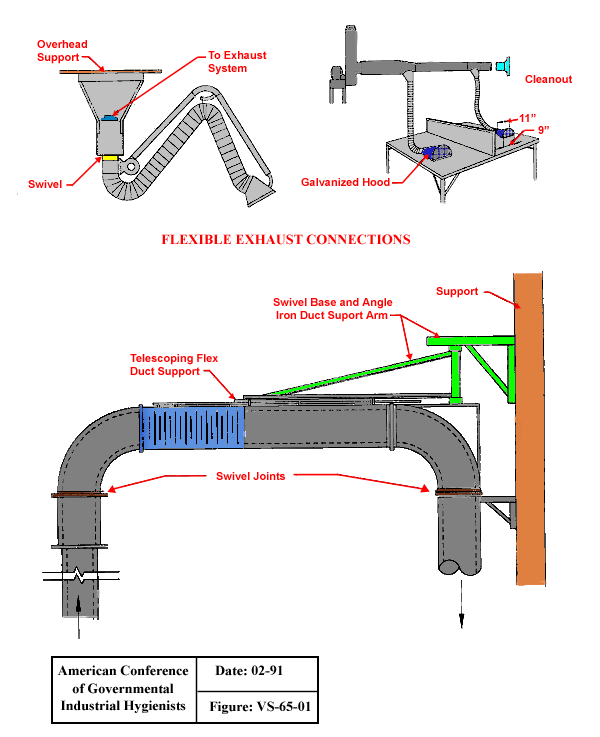
Text Version
Flexible Exhaust Connections
Flexible exhaust connections with overhead support and swivel, with galvanized hood and with telescoping flex duct support, swivel joints, swivel base and angle iron duct support arm and support.
From American Conference of Governmental Industrial Hygienists (ACGIH®), Figure VS-65-01, Industrial Ventilation : A Manual of Recommended Practice, 23rd Edition. Copyright 1988. Reprinted with permission.
Workbench
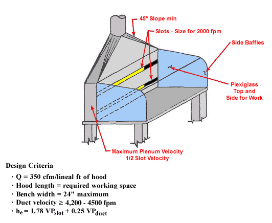
Text Version
Workbench
Workbench with side baffles and slots for 2000 fpm, plexiglass top and side for work, maximum plenum velocity, 1/2 slot velocity.
Design Criteria:
Q = 350 cfm/lineal ft of hood
Hood length = required working space
Bench width = 24" maximum
Duct velocity ³ 4,200 - 4,500 fpm
he = 1.78 VPslot + 0.25 VPduct
Typical System Layout Low Volume/High Velocity
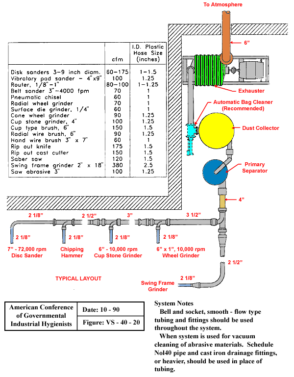
Text Version
Typical System Layout Low Volume/High Velocity with Chart
Typical system shown with piping sizes of 2 1/8" for 7" - 72,000 rpm Disc sander(2 1/8"), 2 1/8" for chipping hammer (2 1/2"), 2 1/8" for 6" - 10,000 rpm Cup stone grinder (3"), 2 1/8" piping for 6" X 1", 10,000 rpm Wheel grinder (3 1/2"), and 2 1/8" piping for Swing Frame grinder( 2 1/2"). Fittings are in parentheses following each machine type. All lines flow into 4" piping connected to primary separator, dust collector, with recommended automatic bag cleaner, and exhauster to atmosphere.
| cfm | I.D. Plastic Hose Size | |
|---|---|---|
| Disk sanders 3-9 inch diameter | 60-175 | 1 - 1.5 |
| Vibratory Pad Sander - 4" X 9" | 100 | 1.25 |
| Router, 1/8" to 1" | 80-100 | 1 - 1.25 |
| Belt Sander, 3" - 4000 cfm | 70 | 1 |
| Pneumatic chisel | 60 | 1 |
| Radial Wheel Grinder | 70 | 1 |
| Surface Dye Grinder, 1/4" | 60 | 1 |
| Cone Wheel Grinder | 90 | 1.25 |
| Cup Stone Grinder, 4" | 100 | 1.25 |
| Cup Type Brush, 6" | 150 | 1.5 |
| Radial Wire Brush, 6" | 90 | 1.25 |
| Hand Wire Brush 3" X 7" | 60 | 1 |
| Rip Out Knife | 175 | 1.5 |
| Rip Out Cast Cutter | 150 | 1.5 |
| Saber Saw | 120 | 1.5 |
| Swing Frame Grinder | 380 | 2.25 |
| Saw Abrasive 3" | 100 | 1.25 |
System Notes:
Bell and socket, smooth - flow type tubing and fittings should be used throughout the system. When system is used for vacuum cleaning of abrasive materials, schedule Nol40 pipe and cast iron drainage fittings, or heavier, should be used in place of tubing.
From American Conference of Governmental Industrial Hygienists (ACGIH®), Figure VS-40-20, Industrial Ventilation : A Manual of Recommended Practice, 23rd Edition. Copyright 1988. Reprinted with permission.
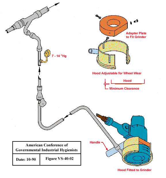
Hood for Cup Type Surface Grinder and Wire Brushes
Text Version
Hood for Cup Type Surface Grinder and Wire Brushes
Hood fitted to surface grinder. Hood is adjustable for Wheel wear with adapter plate to fit grinder.
Design Criteria:
Q = 25 - 60 cfm/inch diameter or width
Branch static pressure = 7 to 14" Hg
Slot velocity = 30,000 to 39,000 fpm
Flexible hose = 1" to 2" ID
Extension hose = Up to 8 ft long*
Peripheral speed = 6,000 to 12,000 linear fpm
*Hose lengths may be extended up to a maximum of 50 ft by using larger sizes between the tool hose and the tubing system.
From American Conference of Governmental Industrial Hygienists (ACGIH®), Figure VS-40-02, Industrial Ventilation : A Manual of Recommended Practice, 23rd Edition. Copyright 1988. Reprinted with permission.
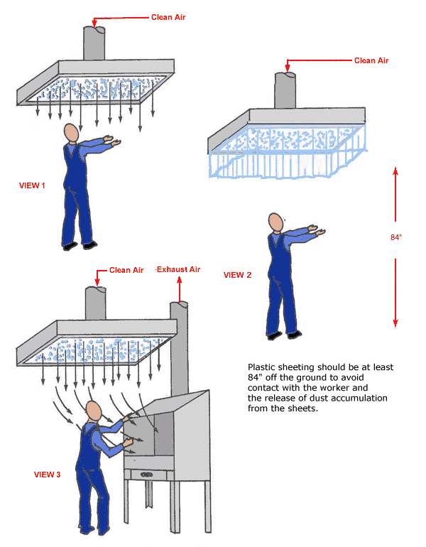
Supplied Air Island
Text Version
Supplied Air Island
View 1 - Flow of clean air through supplied air island
View 2 - Flow of clean air through supplied air island with plastic sheeting (Plastic sheeting should be at least 84" off the ground to avoid contact with the worker and the release of dust accumulation from the sheets.
View 3 - Flow of clean air through supplied air island with exhaust ventilated work station
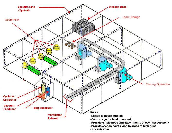
Central Vacuum System
Text Version
Central Vacuum System
Central vacuum system with oxide mills, casting operations, and storage areas showing vacuum lines and ventilation exhaust. Cyclone separator, vacuum producer and bag separator are located outside.
Notes:
- Locate exhaust outside
- Overdesign for lead transport
- Provide ample hose and attachments at each access point
- Provide access point close to areas of high dust concentration
Plan View of Central Vacuum System
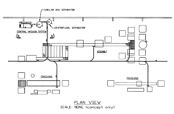
Text Version
Plan View of Central Vacuum System
Central vacuum system with producer, tubular bag separator and centrifugal separator. Feeder flows from finishing, assembly and second finishing area to central vacuum system.
Plan View Scale: None (concept only)
Elevation View of Central Vacuum System
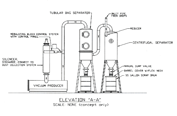
Text Version
Elevation View of Central Vacuum System
Vacuum producer with silencer and modulating bleed control system with control panel flows to tubular bag separator and centrifugal separator with manual dump valve, barrel cover with flex neck and 55 gallon scrap drum. An inlet pipe from drops with reducer is also shown.
Elevation "A-A" Scale: None (concept only)
Schematic View of Central Vacuum System
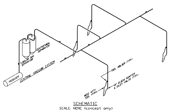
Text Version
Schematic View of Central Vacuum System
Central vacuum system with flows shown to centrifugal separator, tubular bag separator and vacuum producer.
Schematic scale: None (concept only)
Boot Wash Station
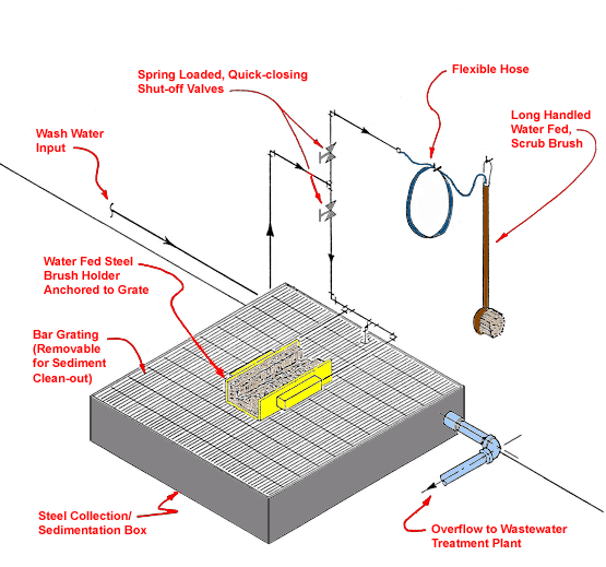
Text Version
Boot Wash Station
Steel collection/sedimentation box with bar grating (removable for sediment cleanout); water fed steel brush holder anchored in center to grate; spring loaded, quick closing shut-off valves; flexible hose; long handled water fed scrub brush; with overflow to wastewater treatment plant
Shoe Cleaning Machine
Text Version
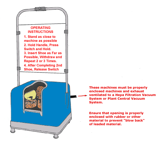
Shoe Cleaning Machine
Operating Instructions:
- Stand as close to the machine as possible.
- Hold handle. Press switch and hold.
- Insert shoe as far as possible. Withdraw and repeat 2 or 3 times.
- After completing 2nd shoe, release switch.
These machines must be properly enclosed machines and exhaust ventilated to a Hepa Filtration Vacuum System or Plant Central Vacuum System. Ensure that opening is properly enclosed with rubber or other material to prevent "blow back" of leaded material.
Clothes Cleaning Air Shower
Text Version
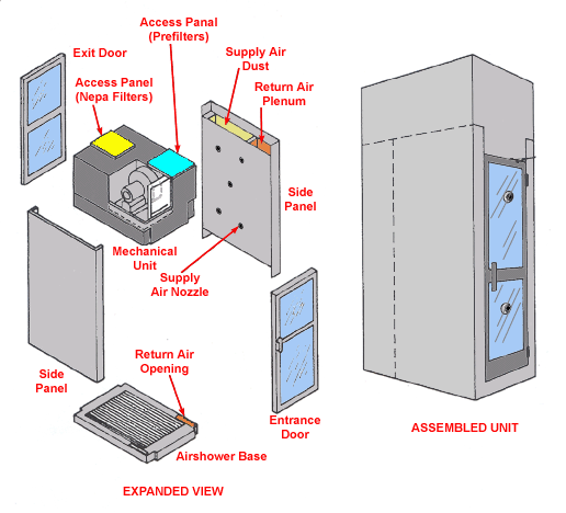
Clothes Cleaning Air Shower
Assembled unit and expanded view with side panels, entrance and exit doors shown with supply air nozzle, return air opening, airshower base. Mechanical unit is also shown with access panels for Nepa filters and prefilters.
Design Characteristics:
- Check with supplier
Application Tips
- Install at entrance to clean-rooms, lunchroom, etc.
- Allow time for full use by employees.
- Provide daily cleaning and maintenance.
Mobile Vacuum
Text Version
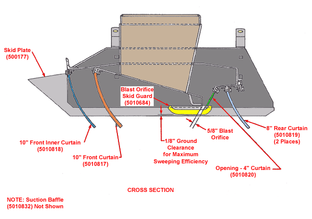
Mobile Vacuum
Cross section of mobile vacuum with skid plate, blast orifice skid guard, front inner curtain, 1/8" ground clearance for maximum sweeping efficiency, 5/8" blast orifice, 8" rear curtain and opening for 4" curtain.
Hygiene Facility
Text Version
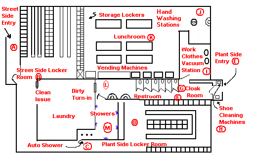
Hygiene Facility
|
Street
Side Entry (A) |
Street Side Locker Room (B) |
Storage Lockers
|
Hand Washing Stations
|
(J)
|
|||
|
Lunchroom
(K) |
|||||||
|
Vending Machines
|
Work Clothes Vacuum Station(I) | Plant side Entry (E) | |||||
| Clean Issue | Dirty Turn-in |
Restroom
(F) |
Cloak Room (G) | Shoe Cleaning Machines (H) |
|||
|
Laundry
|
Showers | (C) | Plant side Locker Room (D) | ||||
| Autoshower (N) | |||||||
Facility Function/Description:
- The facility can be entered from the street at only one point. (A)
- Street clothes are removed and clean work clothes, hardhat, and respirator are issued and donned in the street side locker room. (B)
- The employee passes through a one-way turnstile in order to get to the plant-side locker room. (C)
- The employee dons work boots and other safety gear in the plant-side locker room where they are stored. (D)
- There is only one entry to the plant. (E)
- The restroom just inside the cloak room is readily accessible during working hours. (F)
- The cloak room provides a place to store coats, hardhats, gloves and respirators during break periods. (G)
- During lunch break the employee first cleans his boots at the shoe cleaning machines (H), leaves coat and equipment in the cloak room (G), vacuums off his clothes at the vacuum stations (I), proceeds to the hand washing station where he thoroughly washes his hands (J), and finally enters the lunch room. (K)
- At the end of the shift the procedure is as follows: the employee cleans shoes (H), removes contaminated clothing in the plant side locker room (D), stores boots, etc. in plant-side lockers, turns in dirty work clothes, hardhat and respirator to laundry (L), and proceeds to the showers. (M) He then must pass through an automatic shower (N) to return to the street-side locker room (B), where he dresses and leaves the facility. (A)
Source Characterization
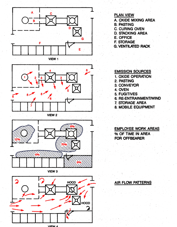
View 1 - Plan View
- Oxide Mixing Area
- Pasting
- Curing Oven
- Stacking Area
- Office
- Storage
- Ventilated Rack
View 2 - Emission Sources
- Oxide Operation
- Pasting
- Conveyor
- Oven
- Fugitives
- Re-entrainment
- Storage Area
- Mobile Equipment
View 3 - Employee Work Areas
% of time in area for offbearer
View 4 - Air Flow Patterns
Paste Mixer with Supplied Air Island above Testing Station
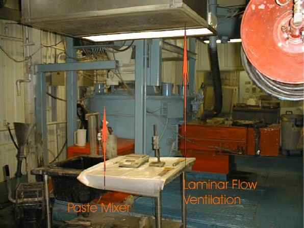
Paste mixer with supplied air island above testing station. Red arrows point to laminar flow ventilation (supplied air island) and to the paste mixer in the background
Intercell Burning Backdraft Hood
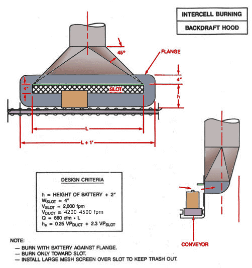
Text Version
Intercell Burning Backdraft Hood
Front view of intercell burning backdraft hood showing flange and slot. Side view of conveyor and hood.
Design Criteria:
h = Height of Battery + 2"
Wslot = 4"
Vslot = 2,000 fpm
Vduct ³ 4,200 - 4,500 fpm
Q = 660 cfm x L
he = 0.25 VPduct +2.3 VPslot
Note:
- Burn with battery against flange.
- Burn only toward slot.
- Install large mesh screen over slot to keep trash out.
Lead: Battery Manufacturing eTool
Lead: Battery Manufacturing » Environmental Controls
Employees may be exposed to lead while servicing and maintaining environmental controls.

